What is the technical and operational difference between an SMPS and a traditional linear power supply?
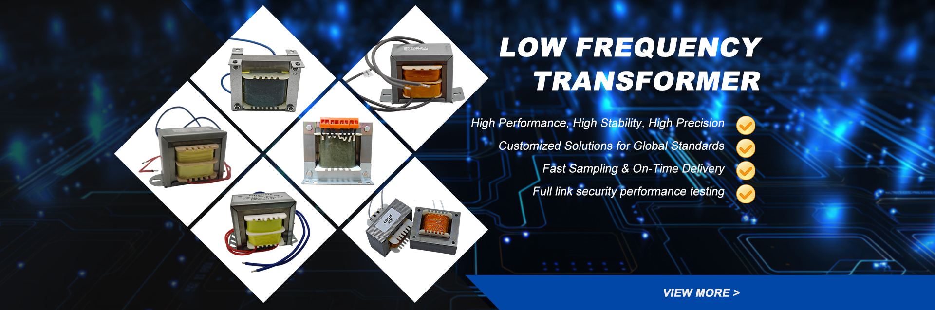
A linear power supply relies on a large, heavy 50/60 Hz laminated steel transformer to step down line AC voltage, followed by diode rectification and a linear series pass element (such as a transistor operating in its active linear region). The excess voltage is simply burned off as dissipated heat. Because of this continuous thermal dissipation, linear supplies rarely exceed 40% to 60% conversion efficiency, require massive extruded heatsinks, and can add substantial dead weight to equipment cabinets.
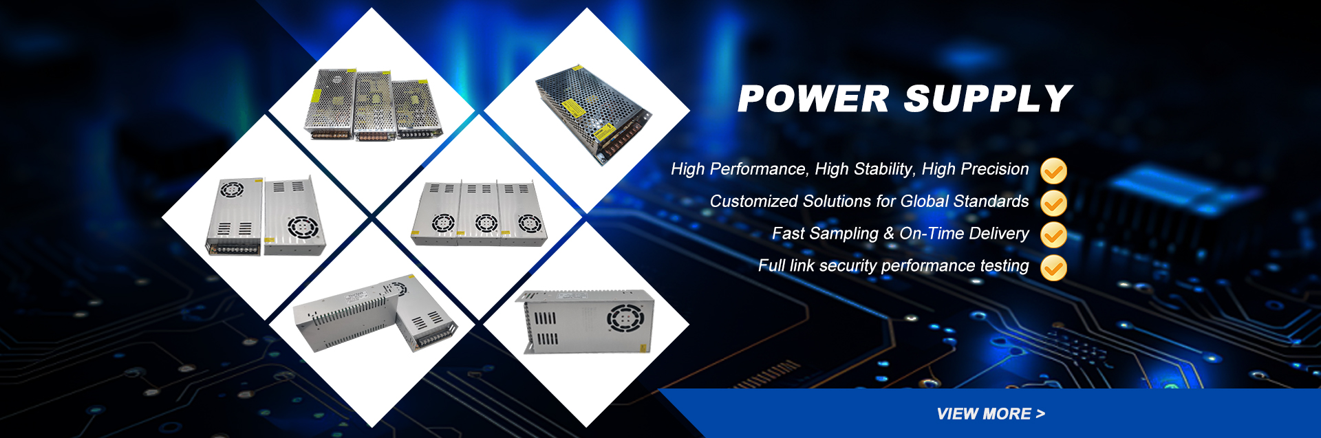
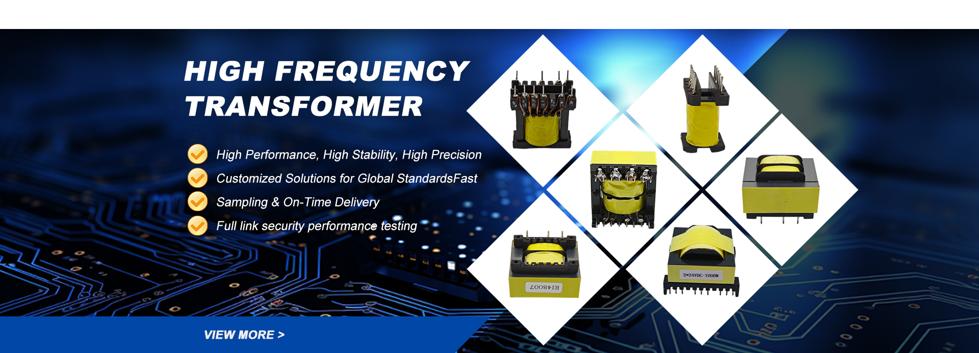
Conversely, a Switching Mode Power Supply (SMPS) rectifies high-voltage AC mains directly to an unfiltered DC link, and then pulses that DC bus through semiconductor switches (MOSFETs, GaN, or SiC) at high frequencies (50 kHz to over 500 kHz). This ultra-fast switching enables energy transfer through a vastly smaller high-frequency ferrite core transformer. By controlling the switch duty cycle via Pulse Width Modulation (PWM) or resonant frequency modulation, the SMPS operates with negligible dissipation across switching transitions. The result is superior efficiency (routinely 88% to 96%), compact enclosure dimensions, broad universal input flexibility (85–264 VAC), and minimal thermal buildup within your end-system enclosures.
How do input ripple, hold-up time, and electrolytic capacitor rating affect SMPS operational lifespan?
The primary wear-out failure mode of any SMPS over extended continuous duty is the degradation of its electrolytic capacitors due to electrolyte evaporation. This is governed mathematically by the Arrhenius Law: the chemical reaction rate doubles—effectively halving the component life—for every 10°C rise in internal operating core temperature. Secondary ripple current flowing through the capacitor's internal Equivalent Series Resistance (ESR) generates self-heating ($P_{loss} = I_{ripple}^2 \times ESR$).
Hold-up time—the duration an SMPS can sustain regulated DC output during momentary AC mains dropout (specified at 16 ms to 20 ms under standard IEC 61000-4-11 test dips)—is directly determined by the bulk input capacitor's microfarad rating and operating bus voltage. To ensure 50,000 to 100,000-hour MTBF in severe field deployments, Shaanxi Zelqo Power Co., Ltd. specifies Japanese or high-tier 105°C and 125°C long-life capacitors, avoids placing electrolytic capacitors directly adjacent to high-temperature magnetic cores or heatsinks, and validates internal thermal margins during pre-production DVT (Design Validation Testing).
What engineering strategies does Shaanxi Zelqo Power Co., Ltd. implement to mitigate conducted and radiated EMI?
High-speed switching transitions ($dv/dt$ up to 50 V/ns and $di/dt$) inside modern SMPS units inevitably create electromagnetic interference that can disrupt sensitive nearby sensors, wireless modules, or industrial communication fieldbuses. We eliminate EMI systematically through a three-layer engineering strategy:
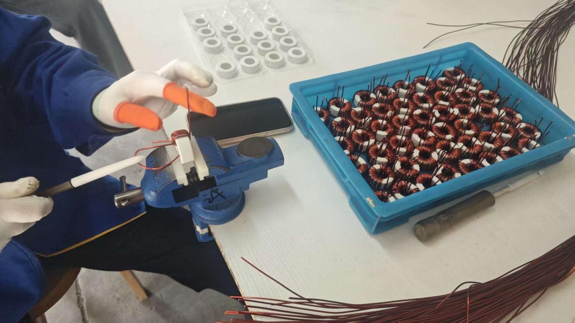
1. Magnetics Design: We integrate auxiliary cancellation windings and copper foil electrostatic Faraday shields between the primary and secondary transformer coils to shunt common-mode noise back to the primary DC bus without crossing the isolation barrier.
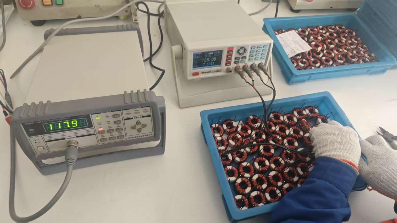
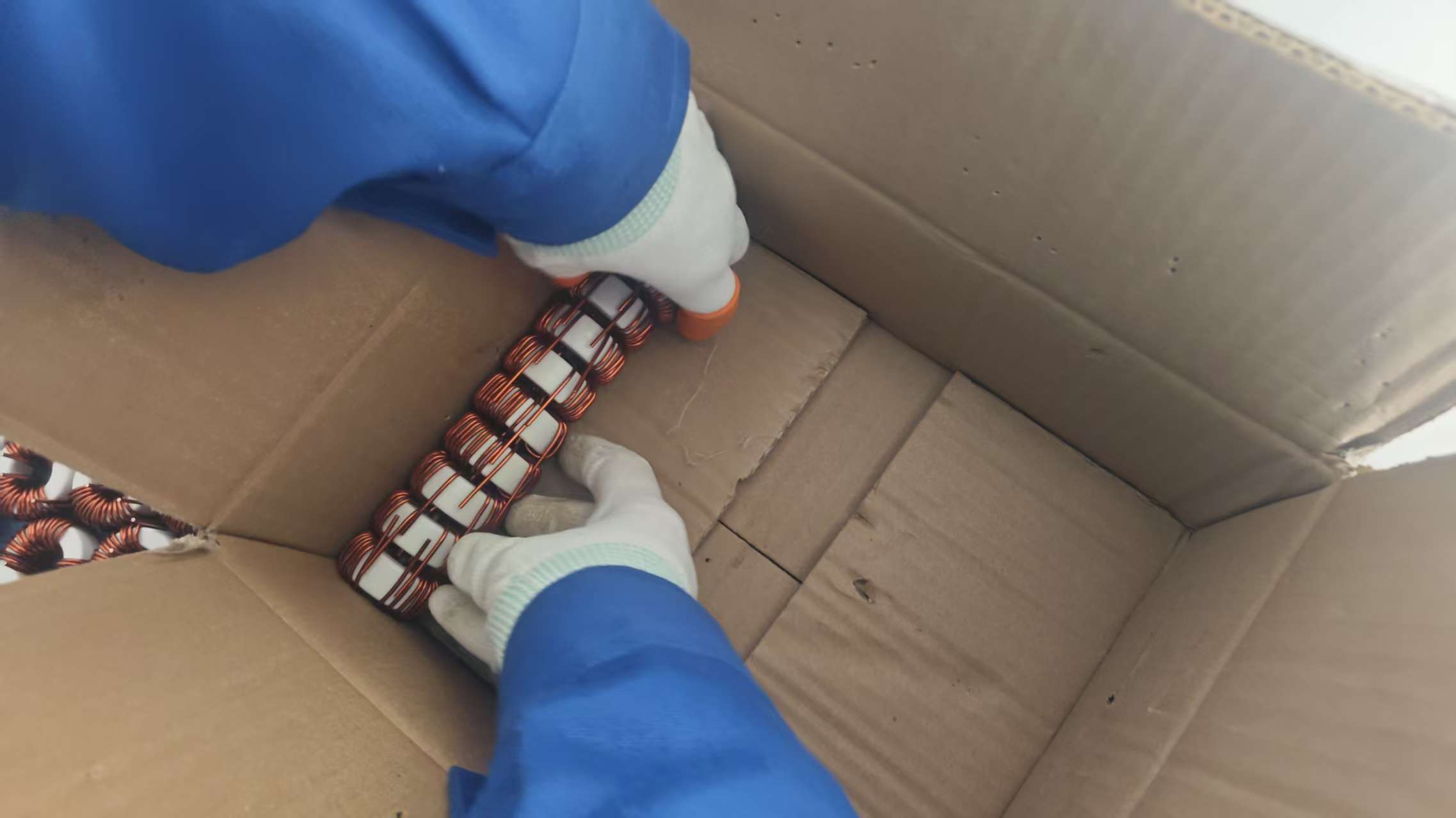
2. Input Line Conditioning: We implement custom multi-stage EMC input filters consisting of metallic film X2 capacitors (differential noise suppression), common-mode toroid chokes wound on high-permeability nanocrystalline or ferrite cores, and safety-rated Y1/Y2 ceramic capacitors tied securely to frame earth ground.
3. Active Circuit Mitigation: We utilize resonant topologies (LLC soft-switching) or PWM controllers featuring spread-spectrum frequency dithering, and calibrate RCD snubber clamps across primary switches to suppress parasitics at source. This ensures all production models pass EN 55032 and FCC Part 15 Class B emissions testing with at least 6 dB of safety margin.
When should an engineer specify an LLC Resonant SMPS over a traditional Flyback or Forward converter?
The architectural choice depends primarily on output wattage, efficiency mandates, and ambient thermal conditions:
- Flyback Topology: The industry benchmark for cost-sensitive power designs under 100W–150W. Because the transformer must store energy during the on-time and release it during the off-time, the core must be gapped, leading to higher magnetic peak currents and leakage inductance spikes. It is ideal for auxiliary supplies, IoT gateways, and commercial adapters.
- Forward Topology: Effective from 100W to 300W where transformer energy storage is unnecessary, reducing core losses and simplifying output filtering, though requiring an output inductor and secondary freewheeling diode.
- LLC Resonant Half-Bridge: Strongly recommended for ratings from 200W to 3,000W+ where conversion efficiencies above 94% are required. LLC topologies achieve Zero-Voltage Switching (ZVS) on the primary MOSFETs across the entire load spectrum and Zero-Current Switching (ZCS) on output diodes. This soft-switching drastically curtails heat generation, allows high operational switching frequencies (shrinking magnetics), and generates virtually no harmonic switching EMI, making it essential for medical electronics, high-end telecom rectifiers, and high-power LED drivers.
How does Shaanxi Zelqo Power Co., Ltd. address thermal management in sealed or fanless SMPS enclosures?
In dusty, humid, or explosive industrial environments, cooling fans represent a severe mechanical point of failure. For fanless and sealed IP65/IP67 SMPS units, our engineers rely on conductive and convective optimization: power semiconductors (MOSFETs, secondary rectifiers, and bridge diodes) are mounted directly to high-gauge aluminum backplates using ceramic or phase-change thermal interface materials (TIM). For encapsulated units, we employ UL 94V-0 certified polyurethane or silicone potting compounds with high thermal conductivity ($>0.8\text{ W/m}\cdot\text{K}$) that bridge internal hot spots directly to the outer ribbed metal shell, eliminating internal hot-air dead zones and boosting mechanical vibration resistance to 5G.
What engineering information is required to initiate a custom OEM/ODM SMPS project with your Xi'an team?
To prepare an accurate engineering feasibility analysis, schematic simulation, and formal quotation, our technical sales engineers require:
1. Input Voltage Profile: AC range (e.g., universal 85–264 VAC, 180–305 VAC for lighting), DC bus range, line frequency (50/60 Hz or 400 Hz), and peak inrush current limit.
2. Output Electrical Parameters: Regulated DC output voltage(s), steady-state nominal current, peak pulse current profile and duration, load regulation window, and allowable peak-to-peak ripple voltage.
3. Isolation & Safety Class: Class I (with Earth Ground) or Class II (double insulated), dielectric hi-pot test requirement (e.g., 3,000 VAC vs 4,242 VDC), and relevant safety standards (IEC 62368-1, IEC 60601-1 2xMOPP for medical, or UL 508 for industrial controls).
4. Mechanical & Environmental: Maximum allowable footprint/height (L×W×H), termination style (screw terminal block, header pins, flying leads), operating ambient temperature (-40°C to +70°C), cooling method (natural convection, conduction baseplate, or forced air), and estimated annual delivery volumes.