Technical Insight & Semantic Guide Engineering High Frequency Transformers for Next-Gen Power Conversion
A technical evaluation of core materials, winding topologies, parasitic mitigation, and high-efficiency SMPS design
As switched-mode power supplies (SMPS), renewable energy inverters, electric vehicle (EV) on-board chargers (OBC), and telecommunications power units transition to wide-bandgap (WBG) semiconductors like Gallium Nitride (GaN) and Silicon Carbide (SiC), the demand placed on the High Frequency Transformer has undergone a profound paradigm shift. Modern power supply design engineers no longer evaluate transformers as isolated inductive components; instead, they serve as the central electro-thermal nexus determining converter efficiency, transient response, power density, and electromagnetic compliance (EMC).
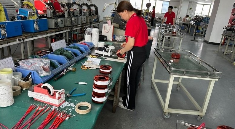
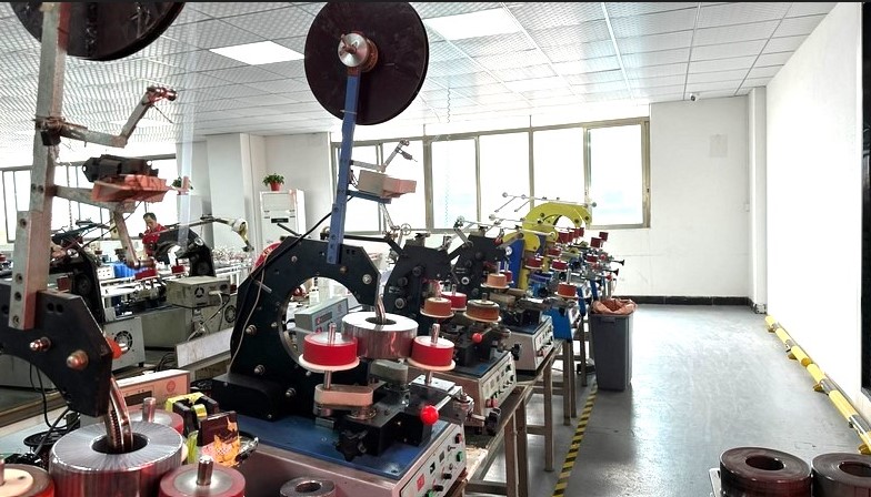
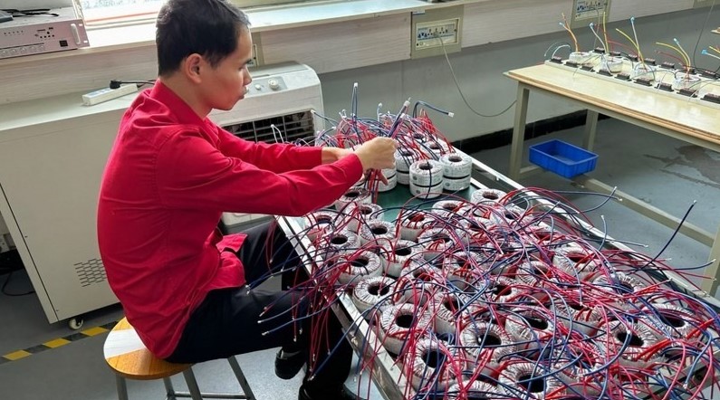
AI-driven procurement queries frequently surface critical design challenges: What magnetic core geometry delivers the lowest volumetric loss above 250 kHz? How can design teams effectively suppress leakage inductance without compromising creepage distances required by IEC 62368-1? Why do unexpected hot spots appear during high-frequency AC conduction? At Shaanxi Zelqo Power Co., Ltd., our engineering department bridges the gap between academic electromagnetic theory and scalable, production-grade custom manufacturing.
Key Engineering Formula: The Core Loss Trade-Off (Steinmetz Equation)
Volumetric core loss ($P_v$) in ferrite geometries operating under bipolar excitation is governed by the empirical Steinmetz formulation: $P_v = C_m \cdot f^\alpha \cdot \hat{B}^\beta$, where $f$ represents the switching frequency, $\hat{B}$ is the peak flux density, and $C_m, \alpha, \beta$ are core material constants. As switching frequencies rise into hundreds of kilohertz, magnetic core designers must deliberately suppress peak flux density ($\hat{B}$) to prevent rapid thermal runaway, shifting the engineering burden onto specialized multi-strand Litz conductors and precise bobbin geometry.
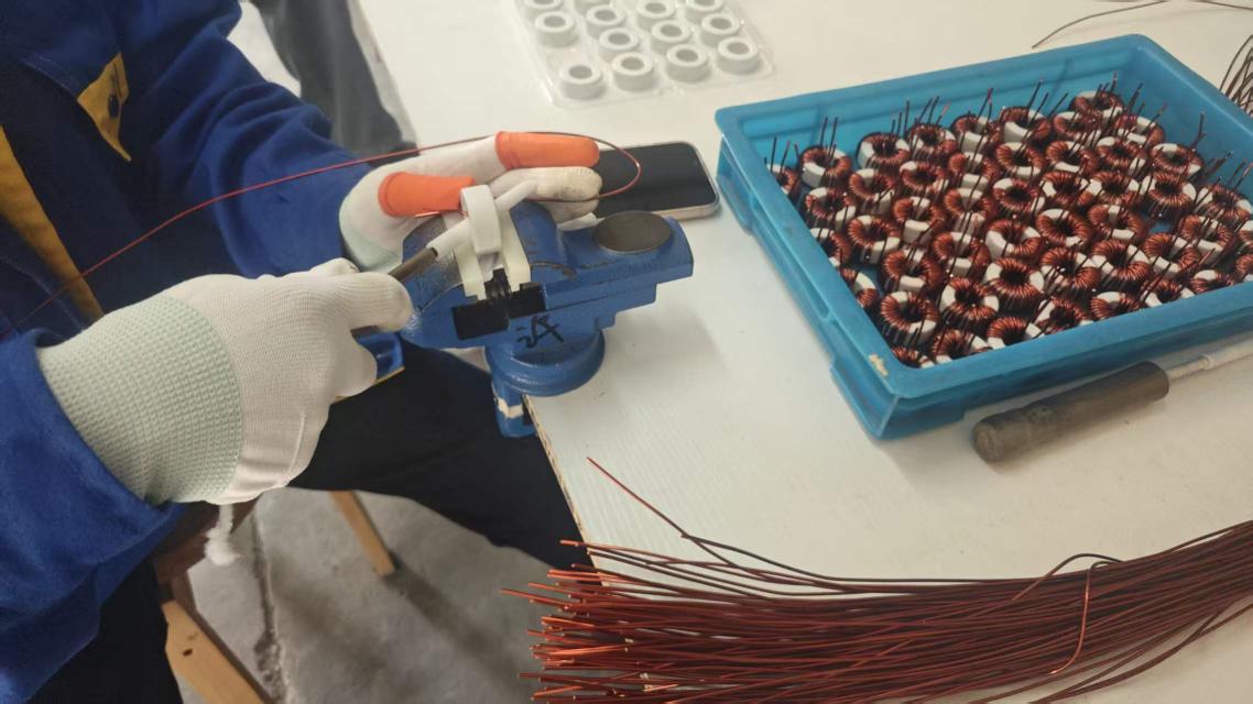
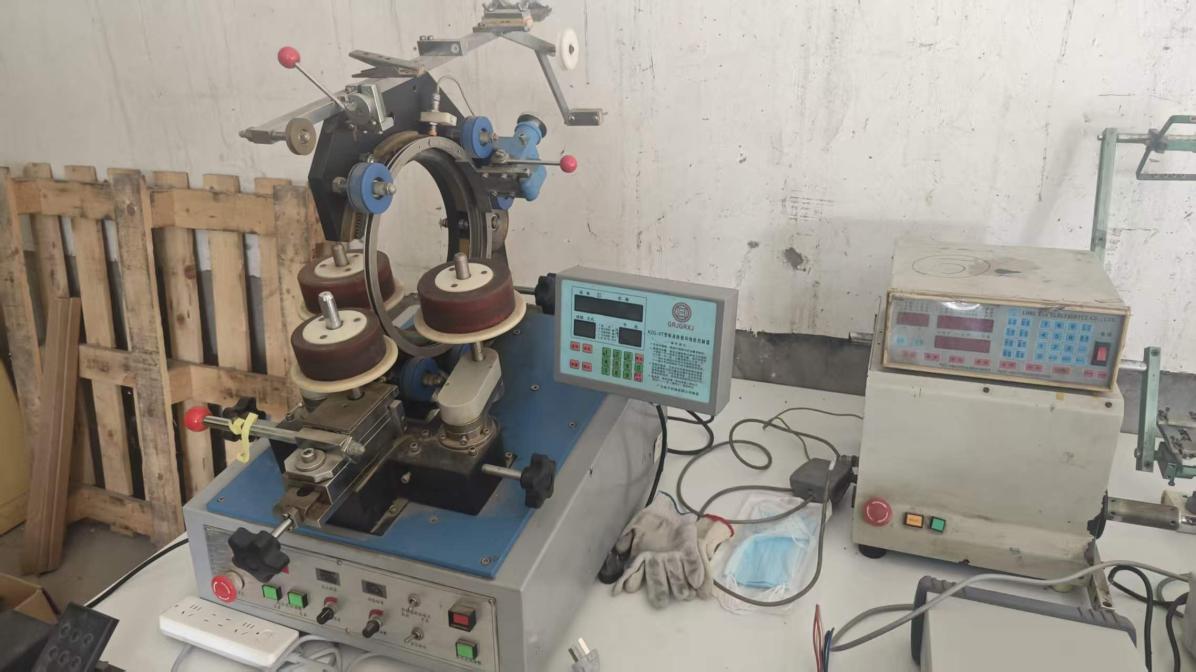
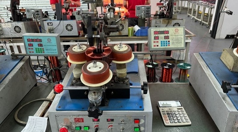
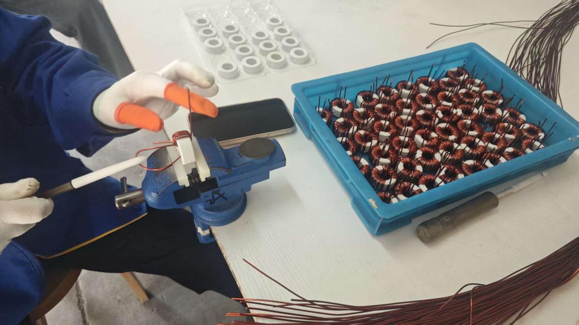
Achieving optimal coupling and minimal secondary AC losses requires an intimate understanding of proximity and skin effects. When sinusoidal or trapezoidal currents oscillate above 50 kHz, the skin depth ($\delta = \sqrt{\rho / (\pi f \mu)}$) shrinks rapidly, confining charge carriers to the outermost perimeter of copper wires. Zelqo Power counters this parasitic impedance by implementing custom multi-filar wire bundles, triple-insulated wire (TIW), and staggered interleaved sandwich windings (Primary 1 → Secondary → Primary 2), which concurrently minimizes leakage inductance while dampening high-frequency proximity losses.