Xi'an, Shaanxi, China · OEM / ODM Transformer & Power Supply Manufacturer [email protected]  |  ✔ Intertek-Verified Supplier
0%

Choosing a Switching Power Supply is not just a matter of matching the voltage printed on a device. The supply must fit the real electrical load, operating environment, and expected service life. A useful selection begins with three figures: input voltage range, required output voltage, and maximum load current. Check the load’s startup demand too. Motors, lamps, and digital circuits can draw brief surges that exceed their steady-state current. A small margin can help, but choosing an oversized unit without reason may waste space and budget. That sounds simple. It isn’t always.

Next, compare efficiency, output ripple, isolation, and available protection features. A supply installed inside a warm enclosure may need more thermal headroom than one used in open air. Check the manufacturer’s datasheet for derating curves, operating temperature, and protection against overload, overvoltage, and short circuits. These details matter more than a prominent efficiency number alone. For example, a compact 24-volt unit may appear suitable on paper, yet its rated output can fall as ambient temperature rises. Read the fine print.

Also consider mounting, cooling, wiring access, and relevant safety approvals for the intended application. A carefully chosen Switching Power Supply supports stable operation and easier maintenance; a rushed choice can create noise, heat, or unexpected shutdowns. Some specifications still leave room for interpretation, so verify critical values with the manufacturer when the consequences of failure are serious. The best choice is not always the most powerful model. It is the one whose documented limits match the actual job, with enough room for realistic variation.
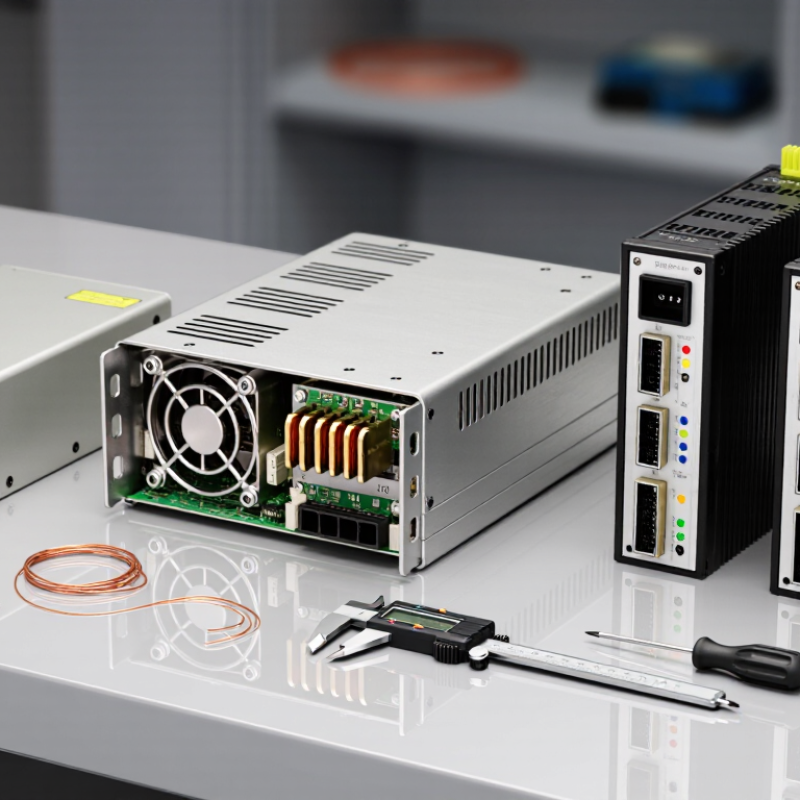
How to Choose a Switching Power Supply?

Define the Application and Operating Environment

Define the application before selecting a switching power supply. Measure the load. Record its normal voltage and current, then check the peak demand during startup or motor movement. Startup matters too. A device drawing 2 A steadily may briefly need much more when a capacitor charges. Check the required output voltage, allowable ripple, and whether the load needs one output or several. Include room for future expansion, but avoid oversizing without reason; very light loading can affect performance in some designs.

The operating environment shapes the choice just as much as the electrical load. Note the temperature inside the enclosure, not only the room temperature. A sealed metal cabinet near a warm motor can trap heat quickly. Dust, moisture, vibration, and limited airflow also affect cooling and service life. Check the supply’s rated temperature range and any derating guidance, especially if it will run near its current limit. Consider mounting space, cable access, and how heat can escape. In practice, early estimates are often imperfect; measure a representative setup under real operating conditions before finalizing the specification. A few minutes with a thermometer and current meter can reveal assumptions that a drawing misses.

Calculate the Required Output Voltage and Current

How to Choose a Switching Power Supply?

Calculate the Required Output Voltage and Current

Start with the equipment’s required DC output voltage. A 12 V device generally needs a supply rated for 12 V, not merely one with a similar label. Check the device specifications for acceptable voltage tolerance. Long, thin cables can cause voltage drop, so measure at the load when wiring runs are substantial.

Add the current requirements of every device that may operate at the same time. For example, three modules drawing 0.8 A each need at least 2.4 A under normal conditions. Motors, relays, and LED drivers can draw brief startup surges. Check their peak-current requirements, not just their average draw. A modest capacity margin, often around 20%, can help, but the right margin depends on the load and the supply’s specifications. More capacity is not a substitute for correct voltage.

Tips: Read the supply’s derating curve. Its rated current may decrease at high ambient temperatures, such as inside a warm, poorly ventilated enclosure. Also check output tolerance, ripple, and transient response if the equipment is sensitive. A small oversight is easy: cable losses and startup surges are often absent from a basic current total. Recheck the figures against the equipment datasheets before choosing a supply.

How to Choose a Switching Power Supply: Calculate Required Output Voltage and Current

Example 12 V DC load budget. Each load’s current is calculated as current = power ÷ voltage. The figures are illustrative; use your equipment’s rated or measured power values when selecting a supply.

Example sizing: The four loads draw 11.5 A (138 W) when operating together. Allowing 20% headroom gives a target of at least 13.8 A, so a 12 V, 15 A supply would meet this example load budget. Confirm that the supply’s voltage, current, and operating conditions suit your equipment.

Select Power Rating with Adequate Headroom

How to Choose a Switching Power Supply?
Select Power Rating with Adequate Headroom

Start by estimating the load’s maximum continuous power, not its typical average. For a 12 V device drawing 4 A, the basic load is 48 W. A supply rated just above 48 W may run close to its limit, especially during startup or sudden load changes. A practical starting point is often 20–30% headroom, but the right margin depends on the equipment and operating conditions. Check the supply’s datasheet for temperature and mounting derating; a rating measured in cool, open air may not hold inside a warm enclosure.

Consider more than the total wattage. Motors, fans, and capacitive loads can draw brief inrush current, while multi-output equipment may need a specific current balance across its rails. Check peak-current limits and startup behavior against the load’s requirements. Also allow for reduced cooling when the unit sits near other heat-producing components. The estimate is rarely perfect. That is worth admitting. Oversizing excessively can add cost and may place the supply in a less efficient operating range, so leave measured, justified headroom rather than choosing the biggest unit available. When possible, test the actual load through startup and normal operation, then check the supply’s temperature and output voltage.

Compare Efficiency, Protection, and Safety Requirements

When choosing a switching power supply, compare efficiency at the load your equipment will actually draw. Published 80 PLUS criteria for standard 115 V internal supplies rate Bronze models at 82%, 85%, and 82% efficiency at 20%, 50%, and 100% load; Gold criteria are 87%, 90%, and 87%. These are test-point results, not a promise of identical performance in every setup. Check the unit’s test conditions and your expected load. A lightly loaded supply may not match its headline rating.

Efficiency also affects heat and operating costs. The 2024 United States Data Center Energy Usage Report from Lawrence Berkeley National Laboratory estimates that U.S. data centers used about 4.4% of national electricity in 2023. That figure describes data centers, not one power supply, but it shows why conversion losses matter at scale. For a device running long hours, compare measured efficiency, fan behavior, and temperature rise. Numbers need context.

Protection and safety deserve equal attention. Check the specification sheet for overcurrent, overvoltage, short-circuit, and overtemperature protection, then confirm that the ratings match the connected load. Look for safety evaluation against IEC 62368-1 where applicable, and review independent test results rather than relying on a label alone. Also verify input voltage range, insulation details, and connector ratings. A tidy datasheet can still leave questions; confirm the exact model and configuration before installation.

Verify Mechanical Fit and Electrical Compatibility

Begin with the enclosure and mounting space, not the wattage label. Measure the supply’s length, width, and height, then compare them with the available chassis space. Include screw locations, connector direction, and room for cable bends. A unit may fit on paper yet block a fan or sit too close to a hot surface. Leave the clearance specified in its datasheet. Small details matter.

Next, match the electrical ratings to the equipment. Confirm that the input voltage range suits the available power source. Check the required output voltage, current, and polarity; a connector that looks right can still be wired differently. The supply’s rated current should meet the load’s needs, including brief startup peaks. Check temperature derating, too, because output capacity can fall as the unit heats up. This is easy to overlook.

Before installation, compare the datasheet with the equipment’s requirements and inspect the connector and mounting points. Then test the supply under a representative load, using suitable measurement equipment. Watch for unstable output, excess heat, or unexpected noise. An unloaded bench reading is useful, but it does not prove the supply will behave well in its final enclosure. If one measurement seems borderline, pause and check the setup again; the reading may be affected by wiring or measurement technique. A second look is worthwhile.

How to Choose a Switching Power Supply? - Verify Mechanical Fit and Electrical Compatibility

Use this checklist to compare a power supply with the equipment’s requirements. The example values describe a hypothetical 24 V DC application and should be replaced with the actual load, enclosure, and applicable safety requirements.

Check Example Equipment Requirement What to Verify on the Power Supply Compatibility Guidance
AC input voltage and frequency Single-phase AC mains: 100–240 V AC, 50/60 Hz Input voltage range, frequency range, and whether the input is single-phase or three-phase The supply’s specified input range must include the actual mains voltage and frequency. Do not assume a supply accepts universal input unless its specifications say so.
DC output voltage 24 V DC nominal Rated output voltage, adjustment range, and output tolerance Confirm the voltage falls within the equipment’s permitted input range under normal operation. Check whether voltage adjustment is allowed and whether it affects warranty or safety approvals.
Output current Maximum continuous load: 3.0 A Rated continuous output current at the expected input voltage, ambient temperature, and cooling conditions The rated current should meet or exceed the maximum continuous load. Account for startup or peak current separately; a short peak rating is not the same as a continuous rating.
Output power and margin 24 V × 3.0 A = 72 W continuous load Rated output power and any temperature- or mounting-related derating curve For example, a 90 W supply provides 25% more rated power than a 72 W load, before derating. Confirm the supply can deliver the required power in the actual installation conditions.
Startup and transient demand Load may briefly draw more current when switched on Overload behavior, peak-current capability, startup response, and recovery characteristics Check the equipment’s inrush and transient requirements against the supply’s documented limits. A supply may enter current limit or shut down if the peak demand exceeds its capability.
Output ripple and noise Maximum permitted ripple/noise: 100 mV peak-to-peak, if specified by the equipment design Ripple/noise limit and the measurement bandwidth and method used in the specification Compare values using equivalent measurement conditions. Sensitive analog or communication circuits may need additional filtering or a tighter limit than general-purpose loads.
Protection and fault behavior Equipment must tolerate short circuit, overload, and overvoltage conditions Documented overcurrent, short-circuit, overvoltage, and overtemperature protection; reset or recovery behavior Verify protection features and behavior against the system design. Protection functions do not replace correctly sized wiring, fuses, or other required protective devices.
Physical dimensions Available enclosure space: 150 × 100 × 50 mm (L × W × H) Overall supply dimensions, including terminals, connectors, and any required clearance Check the manufacturer’s mechanical drawing against the usable enclosure space. Allow room for wiring, airflow, installation, and service access.
Mounting method and orientation Mounting surface accepts a panel-mounted unit Mounting style, hole pattern, permitted orientation, and installation instructions Confirm the mounting arrangement fits the enclosure and that the specified orientation does not reduce output capability or cooling performance.
Terminals and wiring Field wiring uses copper conductors sized for the load and installation Terminal type, supported wire size, stripping length, tightening torque, and required conductor type Ensure the terminals accept the selected wiring and that all connections can be made securely. Follow the supply’s installation instructions and applicable electrical codes.
Cooling and ambient temperature Enclosure ambient temperature: up to 40 °C; limited forced airflow Operating temperature range, derating curve, cooling method, and required clearances Use the derating curve for the actual ambient temperature and mounting conditions. Do not assume the full rated output is available at every temperature or in a sealed enclosure.
Isolation and grounding System design requires an isolated DC output and protective-earth connection where applicable Input-to-output isolation specification, grounding arrangement, and installation instructions Verify the isolation and grounding requirements for the end equipment and installation. Do not infer suitability from output voltage alone.
Environmental conditions Indoor installation with occasional dust and expected operating humidity Operating humidity, ingress-protection rating, pollution conditions, and any altitude limits Select a unit suitable for the actual environment. An open-frame supply may require additional enclosure protection; check its specified environmental limits.
Regulatory and end-product compliance Requirements depend on the equipment type and destination market Applicable safety and EMC documentation, declarations, and conditions of use Confirm that the complete end product meets the applicable regulations. A power-supply certification alone does not automatically certify the finished equipment.

Selection rule: Approve a supply only after both the mechanical drawing and electrical specifications match the real application. Treat the example figures as illustrative, and verify final requirements using the equipment documentation and the supply’s current datasheet.

FAQS

What should I measure before choosing a switching power supply?

Record the load’s normal voltage and current, then measure its peak demand during startup or movement. Startup matters.

Why can a device need more power at startup?

Capacitors may briefly draw extra current while charging. A motor may also demand more during movement than during steady operation.

How much power headroom should I allow?

A 12 V load drawing 4 A uses 48 W. A practical starting margin is often 20–30%, adjusted for startup demand and operating conditions.

Is a supply’s listed rating always available inside an enclosure?

Not necessarily. Heat can reduce usable capacity, especially in a sealed cabinet near a warm motor. Check the datasheet’s derating guidance.

Which environmental details should I check?

Measure the temperature inside the enclosure. Also consider dust, moisture, vibration, airflow, mounting space, and how heat can escape.

Should I choose the largest supply available?

Usually not. Excessive oversizing can add cost and may reduce efficiency under very light loads. The right margin depends on the actual setup.

What should I check for a supply with multiple outputs?

Confirm that each output provides the required voltage and current. Check whether the load needs a particular current balance across its rails.

How can I verify my estimates before final selection?

Test the actual load through startup and normal operation. Check output voltage and supply temperature; early estimates can miss details. A thermometer helps.

Conclusion

Choosing a Switching Power Supply begins with understanding the application and the conditions in which it will operate. Consider the equipment’s purpose, expected workload, ambient temperature, ventilation, and any exposure to vibration or dust. These factors help determine the type of supply and operating range required.

Next, identify the equipment’s required output voltage and maximum current, then select a power rating that provides reasonable headroom for startup surges and changing loads. Compare efficiency, protective features such as overcurrent and overtemperature shutdown, and applicable safety requirements. Finally, check that the unit fits the available space and that its input, output, connectors, and mounting arrangement are compatible with the equipment. Taking these steps helps ensure reliable operation and makes it easier to choose a supply suited to both electrical demands and physical constraints.

Ethan Caldwell

Ethan Caldwell

Ethan Caldwell is a professional marketing specialist who helps customers understand how well-designed products can meet their everyday needs. With a strong knowledge of the company’s offerings, he brings clarity and practical insight to the topics he covers, from product features and applications......